OpenUtilities Substation Help

Lightning Protection Tool

This tool lets the user visually test pole heights and positions for protecting equipment from lightening (lighting protection calculations are not used by this tool). This tool is based on the Rolling Sphere method, and requires input of a sphere radius and the height of the site.

Accessed from:

SettingDescription
Analysis The Rolling Sphere method (which is what the lightning protection is based on) uses an imaginary sphere of radius over the surface of a substation. The sphere is supported by lightning masts and shield wires which provide lightning shielding. A piece of equipment which lies below the curved surface of the sphere should be protected from a direct stroke of lightning.
Lightning Radius

Specifies the radius of the sphere covering the equipment. There are 4 default values to select from:

  • Level I - 20m
  • Level II - 30m
  • Level III - 45m
  • Level IV - 60m

Or, you can select Other from the drop down list which enables the adjacent field where you can manually enter a radius.

Ground Height Specifies the height (above sea level) of the foundation.
Masts Tops This section lists the defined mast tops in the drawing and displays the X, Y, and Z coordinates for each. The Z coordinate represents the height of the mast itself and not the hook point.

The Show Mast check box will highlight the selected mast in the drawing. The mast(s) will remain highlighted as long as this check box is toggled On.

Show mast Enable this option to add a line element representing the lightning protection masts at the specified coordinates.
Add Mast Top Adds a new mast's coordinates to the masts tops list. When you click on this icon, the following dialog displays prompting you to enter the coordinates for the mast.

Enter the X,Y,Z coordinates directly, or you can click the Assign Mast Top icon to pick a point in the drawing for the mast. The coordinates of the selected point will display in the dialog.

Remove Mast Removes the selected mast's coordinates from the masts tops list. This button is only enabled when there are defined mast tops in the list.
Edit Mast Top Allows you to edit the coordinate values of the selected mast top. Displays the Enter Point dialog with the coordinates from the selected masts top loaded. This button is only enabled when there are defined mast tops in the list.
Pick Mast Enables you to select a point on the drawing to specify as a mast and add the coordinates to the masts tops list.
Check All Masts/Cables Click this button to select all of the masts listed in the grid. The masts will remain selected in the drawing until this button is toggled Off.

This option is also available for the overhead cables for the lightning protection system. A separate button is listed under the Overhead cables grid.

Refresh Refresh the information in the mast tops field with any changes made in the drawing.
Overhead cables This area will list any existing overhead cable(s) selected to be included when calculating the protection field.

The Show cable check box will highlight the selected mast in the drawing. The cable(s) will remain highlighted as long as this check box is toggled On.

Pick Cable If there is an overhead cable in the model which is to be considered when calculating the protection field, this allow you to selected it.
Remove Cable Removes the selected cable from the list. This button is only enabled when there are defined cables in the list.
Process Calculates the protection surface and places a MicroStation element as a surface representing the protected area.

Groups Tab

The Groups tab lists the Mast defined in the drawing, You can select multiple masts and group them to form clip volumes which include the selected masts to create a 2D protection diagram.

SettingDescription
Masts and Cables This grid lists the defined masts and cables along with the placement coordinates.
Group Groups the masts selected from the top grid. Select multiple masts to form a group.

The Delete option lets you delete the selected group.

Extract Height This option extracts the height of the equipment within the defined clip volumes.
Create 2D Section Creates a 2D protection diagrams using the clip volumes of the selected groups. An example of which is displayed below:
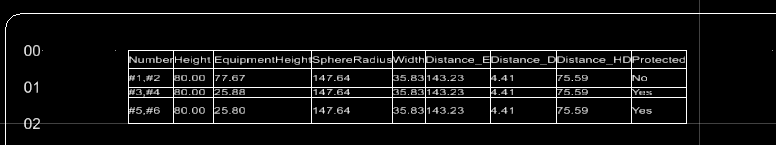
Reports

The reports section displays the protection calculations as well as whether or not the groups are protected or not.

SettingDescription
Protection report template Select a report template from the list.
Run Runs the report and saves the report either on the drawing or to a file.
Send to drawing Allows you to place the report either on the existing drawing or a new drawing. The Text on Drawing dialog displays where you make this determination.

When placing on a new drawing, the New Page dialog lets you define the name and other properties for the page.

Once the new page is defined it is opened in the application and the report is placed on the drawing.

On the new drawing you can reference in the clip volumes that were created.

Send to File Click to save the report to a file. A standand Save As dialog displays so you can define the file name and location to save the report.